Product Description
Professional CNC Machining Parts Supplier-HangZhou XINGXIHU (WEST LAKE) DIS.NG PRECISION INDUSTRY CO.,LTD.-Focus on & Professional
| Material: | Aluminum (6061-T6, 6063, 7075-T6,5052) etc… |
| Brass/Copper/Bronze etc… | |
| Stainless Steel (201, 302, 303, 304, 316, 420, 430) etc… | |
| Steel (mild steel, Q235, 20#, 45#) etc… | |
| Plastic (ABS, Delrin, PP, PE, PC, Acrylic) etc… | |
| Process: | CNC Machining, turning,milling, lathe machining, boring, grinding, drilling etc… |
| Surface treatment: | Clear/color anodized; Hard anodized; Powder-coating;Sand-blasting; Painting; |
| Nickel plating; Chrome plating; Zinc plating; Silver/gold plating; | |
| Black oxide coating, Polishing etc… | |
| Gerenal Tolerance:(+/-mm) | CNC Machining: 0.005 |
| Turning: 0.005 | |
| Grinding(Flatness/in2): 0.005 | |
| ID/OD Grinding: 0.002 | |
| Wire-Cutting: 0.003 | |
| Certification: | ISO9001:2008 |
| Experience: | 15 years of CNC machining products |
| Packaging : | Standard: carton with plastic bag protecting |
| For large quantity: pallet or as required | |
| Lead time : | In general:15-30days |
| Term of Payment: | T/T, Paypal, Western Union, L/C, etc |
| Minimum Order: | Comply with customer’s demand |
| Delivery way: | Express(DHL,Fedex, UPS,TNT,EMS), By Sea, By air, or as required |
/* January 22, 2571 19:08:37 */!function(){function s(e,r){var a,o={};try{e&&e.split(“,”).forEach(function(e,t){e&&(a=e.match(/(.*?):(.*)$/))&&1
| Application: | Fastener, Auto and Motorcycle Accessory, Hardware Tool, Machinery Accessory |
|---|---|
| Standard: | GB, EN, API650, China GB Code, JIS Code, TEMA, ASME |
| Surface Treatment: | Polishing |
| Production Type: | Mass Production |
| Machining Method: | CNC Machining |
| Material: | Nylon, Steel, Plastic, Brass, Alloy, Copper, Aluminum, Iron |
| Samples: |
US$ 10/Piece
1 Piece(Min.Order) | |
|---|
| Customization: |
Available
| Customized Request |
|---|
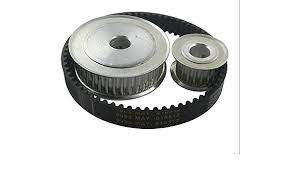
What are some real-world examples of gear pulley systems in action?
Gear pulley systems are utilized in various real-world applications to facilitate mechanical movements, power transmission, and speed control. Here are some examples of gear pulley systems in action:
1. Automobiles:
Gear pulley systems are extensively used in automobiles for various functions. They are employed in the engine’s timing belt or timing chain system to synchronize the rotation of the crankshaft and camshaft, ensuring precise valve timing. Gear pulleys are also found in the accessory drive system, where they drive components such as the alternator, power steering pump, water pump, and air conditioning compressor.
2. Industrial Machinery:
In industrial settings, gear pulley systems are found in a wide range of machinery and equipment. They are used in conveyor systems for material handling, where they drive the belts or chains to transport goods or components along the assembly line. Gear pulleys are also utilized in manufacturing machinery, such as printing presses, packaging equipment, and CNC machines, to control movement, power transmission, and speed regulation.
3. Construction Equipment:
Construction equipment, such as cranes, excavators, and concrete mixers, often employ gear pulley systems. Gear pulleys are utilized in the lifting mechanisms of cranes and hoists, enabling controlled lifting and lowering of heavy loads. In excavators, gear pulleys contribute to the movement of the arm, bucket, and tracks. They are also used in concrete mixers to rotate the drum and facilitate the mixing and pouring of concrete.
4. Mining Equipment:
Mining operations rely on gear pulley systems for various applications. Underground mining equipment, such as continuous miners, utilize gear pulleys to drive the cutting heads and conveyor belts. Gear pulleys are also found in surface mining equipment, including draglines and bucket wheel excavators, where they enable the movement and operation of the machinery.
5. Elevators and Escalators:
Gear pulley systems are an integral part of elevators and escalators, facilitating vertical transportation in buildings. They are used in the elevator’s traction system to drive the hoist ropes or belts, allowing for smooth and controlled movement of the elevator car. In escalators, gear pulleys drive the steps, ensuring synchronized and safe operation as passengers move between different levels.
6. Agricultural Machinery:
Agricultural machinery often incorporates gear pulley systems for various tasks. Tractors utilize gear pulleys in their power take-off (PTO) system, which transfers power from the engine to agricultural implements such as mowers, balers, or grain augers. Gear pulleys are also used in irrigation systems to drive pumps or control the movement of sprinklers and irrigation lines.
7. Home Appliances:
Gear pulley systems can be found in various home appliances, providing mechanical functions. Washing machines, for example, use gear pulleys in their transmission system to control the agitator or drum movement. Gear pulleys are also employed in exercise equipment, such as stationary bikes or rowing machines, to simulate resistance and enable adjustable workout intensities.
8. Wind Turbines:
Gear pulley systems are utilized in wind turbines to convert the rotational motion of the blades into electricity. They are part of the turbine’s gearbox, which increases the rotational speed to match the generator’s requirements. Gear pulleys play a crucial role in the power transmission and speed control within the wind turbine system.
In summary, gear pulley systems are widely employed in various real-world applications across different industries. They are utilized in automobiles, industrial machinery, construction equipment, mining machinery, elevators and escalators, agricultural machinery, home appliances, and renewable energy systems like wind turbines. Gear pulleys contribute to mechanical movements, power transmission, and speed control, enabling efficient and reliable operation in these diverse applications.
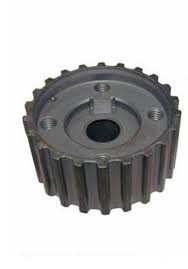
Can gear pulleys be customized for specific machinery and equipment?
Yes, gear pulleys can be customized to meet the specific requirements of machinery and equipment. Customization allows for the adaptation of gear pulleys to fit unique applications, ensuring optimal performance and compatibility. Here’s a detailed explanation of how gear pulleys can be customized for specific machinery and equipment:
Design and Dimensions:
Gear pulleys can be customized in terms of their design and dimensions. The number of teeth, pitch diameter, and overall size of the gear pulley can be adjusted to match the specific requirements of the machinery or equipment. This customization ensures proper fit and alignment within the system, enabling efficient power transmission and smooth operation.
Material Selection:
The choice of materials for gear pulleys can be customized based on the application’s needs. Different materials, such as steel, cast iron, aluminum, or various alloys, can be selected to optimize strength, durability, and resistance to wear and corrosion. The material selection can be tailored to withstand specific operating conditions, such as high temperatures, harsh environments, or exposure to chemicals or moisture.
Tooth Profile and Configuration:
The tooth profile and configuration of gear pulleys can be customized to suit the specific machinery or equipment requirements. Different tooth profiles, such as spur, helical, bevel, or worm gears, can be employed based on factors like load capacity, noise reduction, and efficiency. The gear pulley’s tooth configuration, such as pressure angle, module, and helix angle, can also be tailored to optimize performance and ensure smooth and reliable power transmission.
Gear Ratio:
The gear ratio of a gear pulley system can be customized to achieve the desired speed and torque requirements of the machinery or equipment. By selecting the appropriate combination of driving and driven gears with different tooth counts, the gear ratio can be adjusted to meet specific operating parameters. This customization allows for precise control over the output speed and torque, ensuring optimal performance and compatibility with the application.
Mounting Options:
Gear pulleys can be customized with various mounting options to facilitate easy installation and integration into specific machinery or equipment. Mounting features such as keyways, set screws, or flanges can be incorporated into the gear pulley design, enabling secure attachment to shafts or other components. Customized mounting options ensure proper alignment and minimize the risk of slippage or misalignment during operation.
Surface Treatment and Coatings:
To enhance performance and durability, gear pulleys can undergo surface treatments and coatings customized for specific applications. Treatments such as heat treatment, carburizing, or nitriding can improve the gear pulley’s hardness and wear resistance. Additionally, coatings like lubricants, platings, or specialized materials can reduce friction, enhance corrosion resistance, or provide self-lubricating properties, depending on the operating conditions and requirements of the machinery or equipment.
Special Features:
Depending on the application, gear pulleys can be customized with special features or modifications. This may include the addition of keyways, grooves, or other attachments for auxiliary components, such as sensors, encoders, or brakes. Customized gear pulleys can also incorporate specific tolerances, backlash requirements, or noise reduction features, ensuring optimal performance and compatibility with the machinery or equipment.
In summary, gear pulleys can be customized in terms of design, dimensions, materials, tooth profile, gear ratio, mounting options, surface treatments, and special features. This customization allows gear pulleys to be tailored to the specific requirements of machinery and equipment, ensuring optimal performance, reliability, and compatibility in various industrial applications.
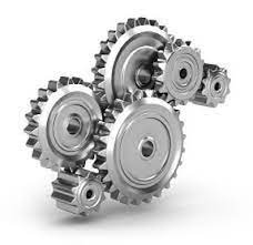
How does the gear mechanism work within a gear pulley system?
In a gear pulley system, the gear mechanism plays a crucial role in transmitting mechanical power between rotating shafts. Here’s a detailed explanation of how the gear mechanism works within a gear pulley system:
The gear mechanism consists of two or more gears with interlocking teeth that mesh together. Each gear has a specific number of teeth and is mounted on a shaft. When the gears are connected within the system, they engage with each other and transfer rotational motion and torque from the driving gear to the driven gear.
Here’s how the gear mechanism works within a gear pulley system:
- Meshing of Gears: The gear mechanism starts with the meshing of gears. The teeth of one gear interlock with the teeth of another gear, creating a mechanical connection between them. The gears are positioned in such a way that their teeth engage properly, ensuring smooth and efficient power transmission.
- Rotation of the Driving Gear: The gear pulley system has a driving gear that receives rotational motion and torque from the power source, such as an electric motor or an engine. As the driving gear rotates, it transfers its rotational motion to the meshed gears.
- Transfer of Rotational Motion: When the driving gear rotates, the interlocking teeth of the meshed gears transmit the rotational motion to the driven gear. The rotation of the driving gear causes the driven gear to rotate in the opposite direction or in the same direction, depending on the arrangement of the gears.
- Speed and Torque Conversion: The gear mechanism enables speed and torque conversion within the gear pulley system. The ratio of the number of teeth on the driving gear to the number of teeth on the driven gear determines the speed and torque relationship between them. When the driving gear has a larger number of teeth than the driven gear, it results in speed reduction and torque amplification. Conversely, when the driven gear has more teeth, it leads to speed amplification and torque reduction.
- Direction Control: The arrangement of gears within the gear pulley system determines the direction of rotation. By meshing gears in specific configurations, the direction of rotation can be changed as needed. For example, meshing two gears with the same number of teeth results in the same direction of rotation, while meshing gears with a different number of teeth causes the driven gear to rotate in the opposite direction.
- Multiple Gear Systems: Gear pulley systems often incorporate multiple gears to achieve specific speed, torque, and direction requirements. By adding intermediate gears, idler gears, or compound gear arrangements, complex gear systems can be created to transmit power efficiently and adapt to the needs of the driven components. Multiple gears allow for more precise control over speed and torque, as well as the distribution of power to multiple output shafts.
The gear mechanism within a gear pulley system enables the efficient transmission of mechanical power, speed and torque conversion, direction control, and the creation of versatile power transmission systems. By utilizing the interlocking teeth of gears, gear pulley systems can effectively transfer rotational motion and torque between rotating shafts, enabling various applications in industries such as automotive, manufacturing, and machinery.


editor by CX
2024-04-30